An article by Heinrich T. Feuerbach
The English and Polish versions are translations of the German original. Downloaded documents and illustrations retain their original languages; existing English versions are used for two diagrams.
In this article · 35
- Theory and practice of asymmetric communication endpoints
- First section.
- Introduction
- Why a theory?
- Introducing a classification of attacks on computers
- Standing on two legs
- Further consequences of asymmetry for computer use, with examples
- Second section.
- The laboratory model as practical proof of implementability and as an example of an implementation using conventional, commercially available means.
- Licence and terms of use:
- Limitations:
- Author: Heinrich Theodor Feuerbach
- Location: Warsaw, Poland
- Starting date of this document version: 7 August 2019
- Version 1.3
- Notice: since 1 August 2020, the entire software package and the hardware have been distributed under GPL v.3.
- General description of the subject matter of the patent:
- Summary and benefits for users compared with present-day solutions for securing Internet access:
- Technical principles used by the invention and their components:
- Security levels of the computers involved in the ACE:
- Red, balun: A3
- Yellow, receiver: A3+C1
- Green, sender: B3
- Structure of the ACE according to ISO-OSI layers
- Layer 1, the physical layer, now additionally the “foundational layer”:
- Layer 2:
- Layer 3:
- Layer 4:
- Layer 5: see Layer 7.
- Layer 6: see Layer 7.
- Layer 7:
- Layer 8:
- Sequence when browsing the web:
- Sequence of the communication described above on Layer 4:
- Attack matrix for systematising all attack paths and targets:
Theory and practice of asymmetric communication endpoints
By Heinrich T. Feuerbach, since February 2019 email: info@feuerbach.info
Copyright belongs to the author. Free for use in Wikipedia articles. Please note: important licensing information. As described further below, I placed both the hardware and the software for the ACE under version 3.0 of the GPL on 1 August 2020. All other licensing notices concerning the ACE are therefore invalid. The full text of GPL v.3.0 is available at https://www.gnu.org/licenses/gpl-3.0.html . For English, click here Overview presentation ACE (.pdf) in English
First section.
Introduction
This article first describes the theoretical background of asymmetric communication in networks such as the Internet and its advantages in terms of data security. This is followed, in a second section, by a description of one possible implementation of an asymmetrically communicating computer system using conventional equipment (Ethernet, PCs). This provides practical proof of implementability. For however clear the security advantages of an asymmetrically operating computer may be, it must be demonstrated that the usual protocols, such as HTTP(S), FTP, Ping, SMTP, etc., can also function under strictly asymmetric conditions. This is by no means trivial, because a method must be found that is generally applicable and requires as few changes as possible to the existing protocol stack and application protocols. I provided this proof in V.0.1, the "Proof of Concept". Both the Ping protocol and the protocol currently used most by end users, HTTP, or its encrypted variant HTTPS, are implemented stably in it. Clarification: "asymmetric communication in networks" does not mean the different bandwidths for uploading and downloading over Internet connections. Rather, the point here is to physically separate the transmitting and receiving functions of a client computer in order to obtain certain physical security advantages. Nor is this about simple data diodes which, for example through optical connections, ensure one-way communication, thus restricting communication to either transmission or reception. To stay with the electrical-engineering analogy of data diodes, the ACE should rather be compared to a bridge rectifier, because the ACE supports both directions of communication. Here I present a framework which, in principle, allows any protocols that have so far communicated only symmetrically to be used under asymmetric conditions. Using an important Layer 3 protocol, the Ping program, and the most commonly used Layer 7 protocol, HTTP(S), as examples, I show that and how protocols can function even under strictly asymmetric conditions. At the end of this page, I offer the source code and installation instructions for download so that a demonstration model based on three laptop computers can be built.
Why a theory?
While considering how best to implement an asymmetric endpoint for networks, I soon discovered that asymmetry has a whole range of implications for data storage and processing. This mainly concerns the distinction, now necessary, between data sources and data sinks, the placement of the ACE in the ISO-OSI model, the distinction between own data and third-party data, the transition from serial to parallel data storage, and many other details which made it clear to me that asymmetry required very fundamental consideration of this new kind of data processing in order to achieve data security as comprehensively as possible and to avoid any gaps. This also concerns the question of use cases: whether and how common, everyday computer applications, such as server-based data processing, web browsing, and active web use such as online banking, etc., can be implemented under asymmetric conditions. What I consider a very useful tool for clarifying security levels in computers in general is the security matrix, effectively a by-product of my work on the ACE. Since the ACE is a system intended to provide protection against any attacks on data and the processes that handle them, there must also be an unambiguous classification of possible attack routes and targets. Otherwise, it is hardly possible to compare systems in terms of their security. I therefore also stress that the ACE model V.0.1 described here in the practical section and in the tarball at the end of the page provides "security against all attacks initiated and carried out over the Internet", in order to show that protection against "built-in" attacks, for example for data espionage, requires more. The theory I present here also allows this protection, in principle complete protection of data-processing systems (C3). I outline below how such a system might be constructed; here, the dimensionality of the data-processing installation is an important aspect. This aspect is another result of the theory presented here. In all my considerations of data security, the distinction between merely relative and absolute data security was especially important to me. Whereas relative data security permits only an estimated security value and therefore cannot provide any guarantees of data security, absolute data security can provide such a guarantee, with mathematical certainty. As an introduction to the subject, I recommend this presentation: Overview presentation ACE (.pdf)
Networked computer systems are being used more and more, and programs and hardware are becoming ever more powerful, but what use is this if the data on them are not protected against being read by third parties? If they can also be manipulated unnoticed or the entire system can be sabotaged so that it can no longer be used? An asymmetric communication endpoint, or "ACE", provides the technical prerequisites for systematically solving these three problems, whatever the application scenarios. This article concerns end-user computers, that is, the mass market, rather than large industrial automation systems such as IIoT systems.
An ACE is a computer system consisting not of just one computer but of two computers which together form the endpoint of a network. One of the two systems serves exclusively to transmit to the Internet or to other networks desired by the user. The other system serves only to receive from that same network. The "asymmetry" therefore refers to the separation of the functions of "sending" and "receiving". To the ACE user, this system nevertheless naturally appears transparently as a single computer networked symmetrically in the conventional manner.
Such a system is secure by physical means against any attacks initiated from an external, known network such as the Internet and also carried out over that network. This protection is therefore even independent of the application software used. Updates and the like are no longer needed to maintain this high level of security. No attacks initiated and carried out over a network known to the user, such as the Internet, can any longer succeed against an ACE. This applies to data espionage attacks, data manipulation attacks, and sabotage attacks. The only prerequisite is that all data requiring protection be stored at least on the sender, or, better still, synchronously on both devices, the sender and receiver, at the same time. For the distinction between known and unknown networks and its significance, see the introduction to the security matrix below.
The sending and receiving devices together then form a "green side" within the ACE, that is, the secure side with regard to attacks of any kind from the Internet. In terms of security level, I place the colour green between "blue" for isolated networks, such as isolated LANs containing, for example, highly sensitive production areas, and "red" for conventional computers connected to the Internet symmetrically, that is, both sending and receiving (symmetric communication endpoints, SCEs). In the following illustrations, I will mark the sending computer itself in "green" and the receiving computer in "yellow", and refer to them accordingly in the text. Green and yellow together therefore form the "green side" of the entire internal ACE network.
The ACE can be used universally, both for network programs such as the web, email, file transfer, etc., and entirely locally for programs independent of any network. The practical solution for implementing an ACE presented further below constitutes a framework on which, in principle, any application protocols can be run asymmetrically. First, the following digression establishes a suitable basis for the further discussion of security levels in an ACE.
Introducing a classification of attacks on computers
To determine the degree of security of a computer system and to compare different systems with one another (for example: symmetric/asymmetric, networked/non-networked), one must first be able to classify all types of attacks on them.
This means that every conceivable individual attack must have its place in the classification, that is, it must be possible to map it onto the classification and place it in the appropriate context.
For this purpose, I have therefore designed an "attack matrix" consisting of nine main fields, which are further subdivided into subfields. Every conceivable known attack on a computer system, as well as any possible attack imaginable in the future, can be assigned a place in it.
A defender will endeavour to protect or cover all nine fields as completely as possible. An attacker is most likely to attack where protection is weakest, where a field is most difficult to cover, and where visibility is also lowest.
Fields can be covered either absolutely or only relatively (expressed as a percentage). Absolute coverage of a field means that an attacker can never succeed. This is possible only when there is a demonstrable safeguard, for example a physical one. All other measures can provide protection only to an estimated percentage.
The ACE can absolutely cover the areas B3 (sender) and (A3+C1) (receiver) for the known networks. In the receiver's case, area A3 of the known networks would be covered by a preceding firewall ("FW").
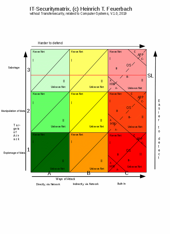
Fig. 1, attack or security matrix of computer systems
Explanations of Fig. 1:
The attack matrix consists of nine main fields with two dimensions: attack routes and attack targets. The fields are further subdivided, primarily into known and unknown networks.
The colours in the diagram have nothing to do with the colours of the networks described above and are independent of them. I chose the colours in the diagram to correspond to the potential danger of the respective field: green is less dangerous, red the most dangerous and most difficult to defend against. The brightness of the colours, which increases towards the top of the diagram, is intended to indicate the visibility of an attack on the corresponding field: the brighter the colour, the more visible an attack is to the user.
A known network exists when someone connects a computer, whether symmetric or asymmetric, to the Internet in a controlled manner. This connection to the Internet is then desired, and the user can also remove it again at any time.
An unknown network exists when someone establishes a connection, for example to the Internet, that is unknown to the owner of the computer or network and is therefore also unwanted by that owner, for example through a mobile phone with data-transmission capabilities connected to the computer, its associated LAN, or a network device, thereby opening an unknown network connection through which data can flow out or in. This inflow or outflow of data is then beyond the control of the user or owner of the computer system or network.
This also includes the unshielded computer monitor when it emits the screen data electromagnetically into the immediate surroundings, as well as an unshielded keyboard cable, unshielded network cables, and so on.
A further subdivision in column "C" separates fields for hardware, operating systems, and application programs. This corresponds to the different areas in which malware, whatever its purpose, may already be built into a computer during manufacture, or after delivery, etc., and may therefore already be present without any network connection at all.
Finally, a further subdivision is made into above and below the visibility line, "SL". Attacks that are directly visible or perceptible to the user lie above the SL; all attacks that are not visible, or not immediately visible, lie below the SL. The SL therefore corresponds to a "waterline": the further below the waterline an attack lies, the harder it is to recognise. Unfortunately, in many cases only sabotage attacks are directly and immediately recognisable to the user.
With the identifiers consisting of Roman numerals (I and II), letters, and minus signs, each individual field can be unambiguously named and distinguished. The characteristic "above" or "below" the SL can also be used.
To name an area consisting of several main fields, one names the field furthest towards the upper right of that area. Individual fields are designated as "field Xn".
Several areas of fields can also be joined with a plus sign, for example (A3+C1).
The common area in the attack matrix that can be covered by both the sender and the receiver through the ACE solely on the basis of asymmetry is the "L" made up of A3 and B1. All other fields can be covered either only by the sender (up to B3) or only by the receiver (up to C1); consequently, asymmetry alone as a measure provides "only" coverage of A3 and B1, including the A3 security of a preceding FW, for the green side, that is, green and yellow together.
The dividing lines in fields C2 and C3 are dashed, because the importance of network connections is limited here: an attack on C2 can take effect entirely without a network, since this means data manipulation by built-in malware. If it is already present on a given computer system, a network is no longer necessary for it to take effect; however, if it is not yet present on a given computer system, a network connection is again necessary for it to spread to other computers. Otherwise, it can act only locally. The same applies to implemented, or built-in, sabotage software, field C3.
Every individual attack can now be assigned unambiguously to one of the fields.
The defender should try to cover all fields, especially those further down.
The further to the right a field lies, the harder it is to cover. The further down it lies, the harder an attack is to detect and therefore to prevent; consequently, the most problematic field for the defender is C1.
Examples of attacks on the individual fields:
Column A, direct attacks over networks: for known networks, these are possible against an endpoint only if no firewall (FW) has been placed in front of it. Unknown networks are unlikely to have a preceding FW, so these are the more likely attack routes. This can occur, for example, through unknown Wi-Fi access, a USB cable connected to one of the computers in the LAN, etc. Unknown communication by ultrasound, as often present in various mobile-phone apps in the form of Trojans, is another possibility.
There are very many possibilities for unknown networks; every listening device attached beneath a conference table constitutes such an unknown network. Infrared, the power grid, etc., can also be used for attacks. Various shielding measures can prevent these, and they can be detected using, for example, sensors.
In column "B", we are already dealing with attacks that are considerably harder to combat, because they come from within, indirectly over the network. Examples include Trojans one "catches" through email attachments. After such an attachment has been opened by the recipient, the Trojan (field B1) collects data such as passwords, emails, etc., in plain text without the victim noticing. In the case of symmetric networking, it then sends these over the Internet to the attacker. Another example is remote control: the Trojan contains a server which allows the attacker to watch the screen contents live at any time without the user noticing anything. Field B2 could mean that the Trojan deletes or modifies files without the user's knowledge. If this serves no purpose beyond causing damage, it is already an attack on field B3, that is, sabotage; but if data are modified in order to achieve a purpose such as manipulating their content, then it is an attack on field B2.
The fields that are most difficult to defend are those in column "C", because here the attack occurs independently of the outside world, that is, the network, and therefore cannot be detected in the network either.
Examples of "C" attacks: a program built into the BIOS of the computer's motherboard that reads keystrokes and sends them directly over the network to a predetermined server on the Internet, where the data are collected. Even reinstalling the operating system cannot remedy this, because the BIOS is not affected. Similarly, malware for espionage, manipulation, or sabotage may be built into any operating system. Application programs often contain such malware or Trojans as well.
To defend against attacks in column "C", it helps to use only trustworthy, tested hardware and software, with open hardware and open software, programs compiled from source, and tests of whether the computers transmit data even without user intervention.
Unknown networks also include unknown protocols, that is, protocols unwanted by the user, even when these unknown protocols run on a physically known network. Thus, at Layer 1, data can be transmitted practically alongside the usual protocols without, for example, an FW noticing anything. Such Layer 1 attacks are equivalent to "flying below the radar" of FWs.
The dimensions of IT security and the possibility of physical defence
The three columns A, B, and C, that is, direct, indirect, and implemented attacks, can be regarded as three dimensions of IT security. A corresponding dimensionality in the ACE can also be used against these attack dimensions to provide absolute defence, at least for the respective fields relating to known networks. For a one-dimensional structure is sufficient to defend against direct attacks: a firewall placed before a computer, with the computer communicating symmetrically, that is, sending and receiving in one device. But if we also want to defend against the second dimension, column B or indirect attacks, then we must also construct the computer in two dimensions, as is the case with the ACE computer described here, because the three "points", sender, receiver, and balun, define a plane, that is, two dimensions. However, this still cannot defend against attacks in column C, implemented attacks already present in the system. For this, we must accordingly construct a computer with three dimensions: by duplicating the sender (while otherwise keeping the same network arrangement). This introduces "height". Duplicating the sender now allows us to compare two senders: we achieve C1 security for the sender by comparing the data traffic on the lines from the two senders towards the balun. If the data traffic is identical, transmission is desired by the user. But if one of the two senders transmits "on its own initiative", a built-in espionage attack is present. To obtain C2 security for the sender, we can compare the own data/files on both senders: if they differ, a built-in manipulation attack on these data is present. Regular, automatic comparison based on hash sums makes it possible to determine which of our two senders was manipulated. Two senders also allow even more secure data storage in the sense of a further parallel backup, as with sender/receiver. For C3 protection of the sender, the processes in both senders can additionally be compared. Such a three-dimensional computer system/ACE therefore allows all three attack dimensions to be secured physically and attacks on them to be detected immediately.
The ACE
A two-dimensional ACE makes it possible, by physical means, to provide complete protection of networked computers against espionage, data manipulation, and sabotage initiated and carried out over the Internet. Such a system is described in the practical section of this article. However, the asymmetry of the two-dimensional ACE alone would not yet provide protection against attacks already built into hardware and software, that is, for example, malware of any kind built into the BIOS, the operating system, or applications. This would require a three-dimensional ACE. Against this very difficult-to-combat type of attack on computer systems, both networked and isolated, helpful measures include examining program source code, open source, open hardware, programs compiled from source, and testing systems to see whether they transmit anything even though the user has neither initiated nor wanted it. Contracts with manufacturers stipulating that there must be no undocumented functions in hardware/software (contractual penalties) can also help here. Monitoring transport and logistics routes is particularly important here to prevent manipulation of the hardware and software.
The technical security of an ACE against attacks over known networks is permanent. This protection is also independent of virus definitions, signatures for network attacks as commonly used in IDS/IPS systems, etc.
The only prerequisite is that the attacker cannot circumvent or break the asymmetry over the network and that it is implemented permanently.
First, the simple explanation of why an ACE is physically secure against espionage over the network and initiated through the network, and why this protection cannot be circumvented by an attacker located somewhere on the Internet: as mentioned, the ACE has a separate computer physically dedicated solely to transmitting to the Internet, and another, physically separate from the first, dedicated solely to receiving from the Internet.
The sender can then transmit to the Internet but cannot receive anything from it; therefore, it can no longer receive espionage attacks (or other attacks) from the Internet which could cause it to transmit data stored on the sender. The same applies to data manipulation and sabotage attacks initiated over the Internet.
The receiver, on the other hand, can receive espionage software from the Internet while browsing, etc., but it can no longer subsequently send the collected data, such as passwords, texts, etc., back to the Internet.
The physically secure separation of sender and receiver is therefore the method for complete security against espionage with regard to those espionage attacks that are both initiated and carried out over the Internet, which probably accounts for the bulk of present-day Internet espionage and data espionage (so-called hacking), that is, industrial espionage as well as spying on individuals such as decision-makers. Just as the hardware of an ACE consists of a sender and a receiver, the software on it must also have corresponding sender and receiver variants.
A conventional communication endpoint ("red") communicates symmetrically as regards communication in the network: a single PC, for example, can both receive from the Internet and transmit to it. The data-flow circuit (sender to receiver and also back to the original sender) is therefore already closed at the application level, Layer 7 in the ISO/OSI model. (The ISO-OSI model was established by the ITU from 1983 and jointly developed by ISO from 1984.) An application can therefore send and receive data without user interaction and thus without any knowledge on the user's part. The browser can send data about the user and data created by the user over the Internet, for example using the HTTP protocol (passwords, etc.). In principle, all other programs on the same PC or end device can do the same. The user who operates the applications cannot prevent this at all; firewalls (FWs) stop only what independently demands access from outside to the inside (PC), but not what travels from the inside to the outside. How could the FW know, and therefore decide, which transmissions from inside are "good" or "desired" and which are not?
Nor is it practical to ask the user whether an application currently attempting to transmit is allowed to do so, because how often must the user then do this? And how can the user always know what application xy wants to send at that moment, and where? And whether this is justified or not?
This "protection" can also be circumvented very easily by smuggling out other data alongside the desired data without the user's knowledge.
The cause of this dilemma is that the "circuit of data flows" (as an analogy with electronics) can already be closed below the user level, namely at Layer 7, as with a server, where it is clear that the server's responses to requests must occur automatically and immediately, for performance reasons alone and without any human intervention.
But what about clients? Which are supposed to be operated only by people? Here, control over when and whether the data-flow circuit is closed, and for what purpose, can and should be left to the user.
An important aspect of ACEs is their invisibility in the network: since the receiver cannot transmit, an attacker cannot get any feedback from it either. For example, it will never respond to an external "Ping". This concerns only the green side of the ACE; the red side will still be able to respond to a Ping.
The sender itself is then no longer reachable over the network, and therefore can no longer be induced from outside to do anything unwanted.
An ACE therefore cannot be controlled remotely either, at least not without the user's conscious involvement.
Indirect protection against DDoS attacks Since an ACE cannot be controlled remotely, it is also the best means against DDoS attacks, that is, distributed sabotage attacks which simultaneously cause many previously compromised computers to send mass requests to specific server addresses in order to bring the servers or clients to a standstill, provided that all users were to use only ACEs as devices for Internet access.
Standing on two legs
As described above, an ACE clearly separates data created by the user from data created by other people outside the same ACE. The user's own data are created on Green so that they can also be sent. If all users used only ACEs, all data would reside on at least one Green device somewhere on the network and would therefore be protected globally against attackers, and thus against all attacks initiated over a network. These data could consequently always be restored from their original on one of the data creator's Green devices. This would prevent the mixing of self-created data (one's own copyright) and data created by other users (someone else's copyright). The ACE would therefore also provide better protection against copyright abuse. One example would be email use with ACEs, in which forwarding emails is prevented and can take place only indirectly through the original sender, enforcing point-to-multipoint distribution of data instead of the point-to-multipoint-to-multipoint distribution customary to date. Unlike symmetrical “endpoints” (SCEs) on the network, with an ACE one stands, so to speak, on two legs rather than just one. This separation between data source and data sink naturally has consequences for the way computers are used.
Further consequences of asymmetry for computer use, with examples
One consequence of working with ACEs is that collaboration by email and with server-side programs must proceed somewhat differently than with SCEs. Emails cannot be forwarded in an ACE, because data must never pass from the receiver to the sender within an ACE, either over the network or manually. An email that has been received must therefore not simply be transferred to the sender and sent from there to other participants in the email exchange. It is, however, easy to send the sender an email asking them to send the same email to additional recipients. This also has the data-protection advantage that copyright must be respected, because the original sender of an email retains control over whom their email is sent to.
The ACE extends the ISO/OSI layer model with layer 8
The familiar seven-layer ISO/OSI model of network communication is extended to eight layers by the ACE, because an ACE is a layer-8 device; see Fig. 2.
The designation “layer-7 device” or “layer-3 device” for a network device derives from the lowest level, or layer, of the ISO/OSI model at which the data-flow circuit is closed for the first time. If one examines the ISO/OSI model upward from layer 1 and identifies the layer at which the data-flow circuit is first closed, that is the layer that gives the device its “layer x” designation. A router, for example, closes the data-flow circuit at level or layer 3 and is therefore a layer-3 device. A repeater, by contrast, is a layer-1 device, because it amplifies signals and thus remains at the purely physical level.
With an ACE, the user retains control over closing the data-flow circuit. The user therefore constitutes the highest layer at which the data-flow circuit can first be closed.
With a conventional “client” computer, an SCE, the user naturally also uses a mouse, keyboard and so on, and the processes in the protocol stack described above are the same as in an ACE. However, the SCE can readily close the data-flow circuit at layer 7, and thus act as a server. Put in deliberately pointed terms, an SCE is therefore merely a server that users also use as a client. An SCE is thus not a genuine “endpoint” in a network, but merely a transit point. This is what makes it so insecure. Since the invention described here lies in layer 1, the physical layer, this also represents an important innovation: the former layer 1 becomes a foundational layer, a foundation. No such foundation existed previously; the physical layer as it has existed so far cannot provide protection or stability for the applications built on it.
Layer 8 is essential for describing ACEs or assigning ACEs within the ISO/OSI model, because the data-flow circuit can be closed only through the user.
The following is a proposed graphical representation of an ISO/OSI layer model extended with layer 8:
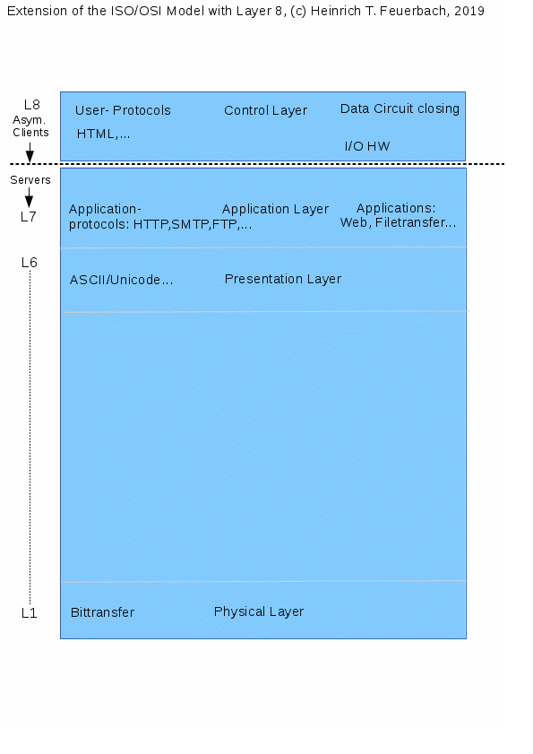
Fig. 2: the layer model extended with layer 8 for ACEs
The ACE also provides effective protection against ransomware
Another important consequence of asymmetry in the ACE is “duplicate data storage”. Here I distinguish between the user's own data and third-party data. The user's own data comprise all data created by the ACE user themselves, for example with a keyboard. Third-party data comprise all data received over the network from other creators on the receiver. Since all of the user's own data in an ACE are entered synchronously into the sender and receiver at the same time using a special keyboard (see the description of a laboratory model further below), the user's own data are always present on both sides, sender and receiver. This duplicate storage allows the receiver to be quickly restored to its previous state following a malware attack. To do this, the receiver is reinstalled from an operating-system image, and after restarting, the user's own data are copied from the sender to the receiver over the synchronization connection, so that both sender and receiver once again have the same state of the user's own data. This restoration procedure also has considerable advantages over backups: because backups of conventionally, symmetrically communicating computers are connected “in series”, one after the other (data source to computer to backup), the backup may already have been infected by the same malware and may therefore be unusable. Malware often has a “time-bomb effect”: a deliberate delay before activation ensures that all backup generations are infected before the user even becomes aware of the attack. Another disadvantage of backups is that they are never current; as a consequence of the serial arrangement, they always contain older data than those the user is currently working on. An ACE, by contrast, operates in parallel on two computers. The data kept in duplicate in the ACE are therefore always current. If the user discovers that they have fallen victim to a ransomware attack, all they need to do is reinstall the receiver from an image and then copy their own data from the sender to the receiver over the synchronization connection. There are also third-party data, meaning data originating from other authors that have been received over a network such as the Internet and “accumulate” on the ACE's receiver over time. To allow these to be restored after reinstalling the receiver as well, the proxy on the Red device also stores the third-party data locally on Red. From there, they can also be restored over the ring connection from Red to the receiver. The receiver is then once again in the same state as before the ransomware attack and is also free from malware received from the network. This assumes that the ransomware is not also copied back from Red to the receiver; close attention must therefore be paid to which third-party data are copied back onto the receiver. To identify file manipulation as early as possible, rather than only ransomware, and to replace manipulated files with their originals, I recommend extensive use of asymmetric cryptography: if all users electronically sign their files before sending them, application programs can check every file against its signature before opening it, identify manipulation and prevent damage from the outset. In principle, website authors could also sign their pages before publication, so that browsers could then apply this signature to the pages and warn the user if manipulation occurs, such as changes to links on the page, or not load the page at all. Unfortunately, these protective possibilities are currently used only to a very limited extent. The combination of asymmetric cryptography (ACR) and asymmetric endpoints (ACE) also has the decisive advantage that the two methods remedy each other's respective weaknesses. The weakness of ACR is that, on symmetrically communicating computers (SCEs), attackers can observe or manipulate the signing and encryption process over the network. This can no longer happen with an ACE: the signing and encryption process on the sender is protected against all outside access. Conversely, ACR protects the ACE's weak side, the receiver. Although considerably less so than with an SCE, the receiver is exposed to write and sabotage attacks and is therefore only “semi-private”. If, as mentioned above, all files are protected with electronic signatures before being sent, such write attacks are no longer possible, or at least can no longer remain unnoticed. ACR protects data in transit and makes “data movements” private. The ACE additionally protects data at rest and makes the computers themselves private as well.
Second section.
The laboratory model as practical proof of implementability and as an example of an implementation using conventional, commercially available means.
In the following section I describe the practical implementation of an ACE.
Important notes on using the files in the tarball below for the ACE V.0.1 laboratory model, programs and hardware derived from it, and all information on this page. These notes take precedence over those in the tarball:
Licence and terms of use:
The files in the tarball available for download at the end of this page are intended to help readers understand and physically reproduce a proof-of-concept (PoC) ACE. Patent and licensing notice: publication of this laboratory model means that nobody can subsequently patent this invention in the form described here. The technical state described on this page therefore constitutes a global starting point for all interested developers to build on in working toward an ACE that will in future be usable by all Internet users.
The source code in C and Bash scripts is included in the files in the tarball.
Publication on “Wikipedia” on the Internet is permitted without restriction, provided the author is credited.
I would appreciate being informed of all new projects to further develop the ACE; I will then be happy to list them on this website.
In some cases I have used publicly available source code distributed under the GPL, specifically the “Ping” utility, part of the FSF network utilities. My “aping”, derived from it, is therefore also distributed under the GPL.
All other programs, however, such as cproxy, lproxy and the various scripts included in the tarball, are not based on GPL-licensed programs but are exclusively my own work. Since 1 August 2020, the provisions of GPL v.3.0 ( https://www.gnu.org/licenses/gpl-3.0.html ) have also applied to them.
Limitations:
I accept no liability and/or responsibility whatsoever for use of the ACE described here. In this form (V.0.1), it is not yet suitable for production use, but is intended solely to demonstrate the general validity of the theory.
It is therefore primarily a demonstration device, a laboratory model.
In particular, this version 0.1 proof of concept still contains the following problems that need to be solved:
1. If only 1000BaseT Ethernet interfaces are used and the auto-crossover function is enabled on all four interfaces in the ring inside the ACE, there is a 50% probability that the four-pole asymmetric ring will run in the wrong direction, counterclockwise, allowing the sender to receive data from Red and the receiver to send data toward Red, the balun, thereby losing its asymmetry. Such a loss of asymmetry naturally completely removes the ACE's high level of security based on asymmetry. This can be corrected manually by starting Ping on the sender after system startup, only on the sender, and observing whether, after the link LED lights up, the data LED on the Blue interface flashes in time with the pings. If it does, this means the ring is running counterclockwise. Ping-request packets are then passing from Green to Blue instead of from Green to Red. By unplugging and reconnecting the RJ45 connector on the Blue interface, the ring can be renegotiated until the Blue interface no longer flashes in time with the pings. Packets now go to Red as they should, and the ring runs clockwise. Under the conditions mentioned above, it can also take up to two minutes for a link in the ring to be established.
If at least one of the four interfaces in the ring did not have an auto-crossover or auto-MDI/MDIX function, or if that function were disabled, for example on Green, the problem described would not arise and the ring would always run clockwise immediately after the ACE was switched on. Nor could it subsequently be reversed, for example by briefly switching off one of the four interfaces participating in the ring. Older Ethernet cards for installation in PCs can occasionally still be found that support a maximum of 100BaseT and do not have auto-crossover built in. Such cards are ideal for the ACE. Proposed solution: see the proposed solution under point 2. This also provides a high level of protection against loss of asymmetry and attacks over the synchronization connection even when only 1000BaseT interfaces and auto-MDIX are used.
2. Received packets on Green's synchronization interface. Normally, the interfaces of the sender, Green, should not receive any packets even after prolonged operation, but should only send packets. This can easily be checked on Green using “ifconfig”, for example. After prolonged use of asymmetric Ping, “aping”, and asymmetric browsing, both of Green's RJ45 Ethernet interfaces should show RX=0. Only TX may show any value greater than zero.
On Yellow, the receiver, both RX and TX may be greater than zero, since Yellow is after all allowed to send “into the Blue”, the terminating interface.
Because the firewall rules are not immediately active at the very beginning while the computers participating in the ACE are booting, a few packets, between 4 and 15, pass from Yellow to Green over the synchronization link. This can easily be prevented by connecting the synchronization-link cables only after booting. Proposed solution: in the balun, route every wire pair through double-pole relays that are open in their unenergized state. This requires six small 5-volt PCB relays, simply operated from a 6-volt battery. Depending on the battery, series resistors are required. A simple changeover switch can then turn on all six relays simultaneously, allowing all six data connections in the balun, ring and synchronization, to be switched on at the same time after the laptops or PCs have already booted. Switching on the ring interfaces simultaneously means that auto-MDIX is not used at all, the link is established immediately and the ring runs clockwise, in the correct direction. Since this also switches on the synchronization connection only after computer startup, no packets can pass from Yellow to Green before the firewall rules are active. In addition, a further script started at system startup frequently checks the output of “ifconfig” on Green, at least once per second, to determine whether a) “RX-Bytes” on both of Green's interfaces are zero, and b) both interfaces always have the “running” status in the respective ifconfig output. If either or both conditions cease to hold, the script should shut Green down, first leaving a log entry indicating which event triggered the shutdown. Such a simple script can then effectively prevent both attacks over the synchronization connection from Yellow to Green and attacks that remove asymmetry. Attacks of this kind can also be easily detected and remedied, followed by reinstalling Yellow. Red and Yellow should also start a similar script with the system, except that it should check these computers only for the “running” status of the interfaces participating in the ring. If “running” is absent from the “ifconfig -a” output, Red and Yellow should likewise be shut down. This prevents the ring from running counterclockwise, the wrong way, after link renegotiation, for example following the unplugging and reconnection of one of the cables participating in the ring. That would remove the ring's asymmetry, which must be avoided at all costs. Since the user only switches the ring on after the computers have booted, as in the relay circuit described above, immediately after system startup the interfaces naturally do not yet have “running” status; they acquire it only after the balun is switched on. The scripts must therefore be able to recognize and tolerate an initial state without “running”, for example by setting a flag as soon as “running” is present for the first time after switch-on. Shutdown should begin only if the flag is set but “running” status is no longer present. A pleasant side effect is that all three computers can be shut down at the same time by switching off the balun, which also tests the protection against loss of asymmetry. Another test of the ring protection consists of unplugging any one of the ring's cables. All three computers should then likewise shut down automatically.
3. “aping” is run with Red as the computer to be pinged, as a test of the ACE's internal connections and proof that layer-3 protocols can be made asymmetric. A wider-ranging test involving computers outside the ACE can also be performed, but IP forwarding on Red, including the iptables firewall and so on, must first be configured, by ticking a box in Yast2 network settings.
4. The runtime indication, the so-called round-trip time, in aping is accurate only to less than one second because of the receiver's time synchronization with the sender. For accurate ping measurements in the external network, I therefore recommend using symmetric, “normal” Ping from Red.
5. At present, only passive browsing is possible asymmetrically, with any browser, which merely needs to be set to use a proxy. Active use, such as logging in or entering passwords for a host, entering data into server databases from the ACE and similar operations, has not yet been implemented.
6. Automatic loading of images, scripts and so on belonging to a webpage has not yet been implemented. Passive browsing therefore takes place using “raw HTML”.
7. Images on webpages can be loaded manually using a short link. They are then displayed in the browser, and “Alt-Left Arrow” on the synchronous keyboard returns to the webpage. Not loading a webpage's files automatically is naturally more secure.
8. To prevent built-in spying functions in the operating system or application programs from using the “way out” over TCP port 80, long links such as “www.feuerbach.info” are also entered as “y.www.feuerbach.info”. The proxy on Red checks requests arriving on port 80 for this initial “y.”. If it is present, the request is forwarded to the Internet. If it is absent, the request is discarded and logged by the proxy on Red.
This is only a very simple form of protection providing C1 protection on Green. In future, attackers could easily circumvent it, so it should be replaced by better protection, for example in the proxy on Red. This would also remove the need for “y.” before every long-link entry in the browser.
9. With a gigabit connection between Green and Yellow, the speed must be reduced to 100 Mbits for file transfers using “greenfiler”, because the server on Yellow is not designed for 1000 Mbits. Otherwise, files sent from Green to Yellow are stored there with the wrong size.
The following is the general description of the laboratory model, PoC:
Patent description relating to the patent claim * “Asymmetric Communication Endpoint”, ACE for short
Author: Heinrich Theodor Feuerbach
Location: Warsaw, Poland
Starting date of this document version: 7 August 2019
Version 1.3
Notice: since 1 August 2020, the entire software package and the hardware have been distributed under GPL v.3.
*) For important reasons, I waive patent claims for the ACE in the implementation presented here. For details, see README.odt in the same tar.gz file. The licence terms on this website nevertheless take precedence.
Notice: on 1 August 2020, I changed the licensing terms so that all program components are now covered by GPL v.3, GNU General Public License 3. All older licensing notices are consequently invalid. This also applies to the notices concerning licensing and terms of use in the files available for download on this page.
General description of the subject matter of the patent:
A computer system as an end-user device based on three personal computers or laptops,
in general, three end-user computers, to provide better protection of locally stored data and processes against external attacks over a known network, such as local area networks, LANs, and remote networks such as the Internet. The aim is the almost complete security of at least one of the three computers in this system against all direct and indirect attacks initiated and carried out over the Internet or other known networks. In particular, this is intended to defend against attacks over a network such as the Internet that serve data espionage, data manipulation or sabotage. To achieve this aim, the transmitting and receiving functions that networks provide to computers are structured asymmetrically and therefore distributed across two computers. This asymmetry or separation means that the data-flow circuit can be closed only through the user themselves, rather than automatically as with conventional, symmetrically networked computers. This therefore presents a layer-8 device for the first time. Layer 8, or the user layer for user control of data flow, as an extension of the ISO/OSI seven-layer model, thus constitutes an endpoint in networks for the first time. Unwanted network communication is reliably prevented by physical means. This includes cross-connections that webpages establish, without the user's knowledge, to external servers unknown to the user when the user visits webpages. Such cross-connections, which also reduce browser performance, serve to collect data about user behaviour. Nor can “Trojans” spy out any data, because they can enter only the receiving computer and cannot send anything back to the Internet from there. On such a layer-8 device, or ACE for short, data-manipulation programs used, for example, to extort the user by encrypting their data can cause damage only on the receiving system. They cannot do so on the transmitting system, because asymmetry prevents them from reaching it. On the transmitting system, all data and processes are physically protected against all attacks from the network. It follows that, if only ACEs are used, only data that have been sent can be attacked and manipulated, but not the data sources on the transmitting systems themselves. The data sources are therefore no longer accessible over the network; after any kind of attack, their data still exist in the original on the corresponding transmitting system. An attacker can consequently damage only copies of data, not the originals. The data cannot be spied out at all, either from the original or from the copy, for the reasons given above. Processes in the ACE can no longer be observed by means initiated over the network.
Patent claim:
According to the invention, a computer system connected to and enabling the use of the Internet or other networks known to the user, which provides protection of the user's data and processes against attacks initiated and carried out over the Internet.
“Computer systems” here means all data-processing systems built primarily for use by individual people.
This corresponds to “B3 security for known networks”; see the description of the “attack matrix” below and the document “Theory of ACEs” by the same author on firewalls.feuerbach.info. Whenever these security levels are referred to below, only the area of known networks desired by the user is meant. Risks to the user's data and processes from networks unknown to the user, and protection against such networks, are not the subject of this patent application. Likewise, risks to the user's data and processes, and protection against attacks on them by malicious programs already included from the outset, at manufacture, in the hardware, operating system or applications, are not the subject of this patent application.
The security levels or level of protection achieved are:
1. A1 and B1 security: all direct and indirect attacks aimed at data espionage that can be initiated and carried out over the Internet, for example using “Trojan horses”, keyloggers, malware-infected webpages, remote-control tools, exploitation of errors such as “zero-day exploits”, and so on.
2. A2 and B2 security: all direct and indirect attacks that can be initiated and carried out over the Internet and are intended to manipulate data stored or created locally on the computer system, as well as
3. A3 and B3 security: all direct and indirect attacks aimed at sabotaging a computer system that can be initiated and carried out over the Internet and are intended to render the computer system or its data or processes unusable temporarily or permanently.
Since the computer system according to the invention is principally built from two working computers for the user and one auxiliary computer, the security levels stated above assume that the user of such a computer system stores their data at least on the system marked “Green”, the sender, S, and processes them there; depending on requirements and the use case, also on the device marked “Yellow”, the receiver, E.
Indirectly, protection is also provided against DDoS attacks in which very large numbers of “hijacked” conventional computers on the Internet are misused for denial-of-service attacks: if all end users use only ACEs, these can no longer be misused for DDoS attacks either.
Summary and benefits for users compared with present-day solutions for securing Internet access:
This invention provides the level of protection specified in the patent claim for network endpoints while allowing the user of the endpoint to continue using the network, for example the Internet, for customary applications such as browsing the Web (“WWW”). It is therefore a technical protection method situated between, on the one hand, the technical methods customary today involving individual computers connected to the Internet and protected, at most, by firewalls, IDS/IPS and antivirus software, or networks of such computers, and, on the other hand, individual computers and networks of such computers that are not connected to the Internet at all for the purpose of protection (“isolated computers”, “isolated networks”).
Although the isolated computers or computer networks mentioned above are very secure, they considerably complicate operational workflows and require separate computers connected to the Internet simply to use network or Internet services such as email or browsing. Exchanging data between these two worlds is scarcely possible and is also undesirable for security reasons.
Existing computers connected symmetrically to the Internet, that is, sending and receiving at the same time, are in turn exposed to a wide variety of attacks from the Internet. The various protective measures, such as antivirus solutions, also often lag behind attackers and, above all, do not constitute systematic protection against network attacks.
The benefit of the invention described here is therefore that the Internet can continue to be used, with a connection to the Internet remaining available for Web browsing, file transfer, teamwork and so on, while the data and processes are systematically protected against being spied on and against manipulation and sabotage originating from the Internet, that is, from “hackers”.
According to the invention, protection against technical network attacks is achieved systematically in such a way that this protection also applies to future and generally still unknown forms of network attack and does not depend on signatures and similar measures being up to date.
The fact that the end device used by the user of the invention consists of three computers is concealed from the user when using the Internet, for example for Web browsing; the user can use and operate the system as a single device or unit, that is, like a device with one keyboard, one mouse and one screen. The invention makes do largely with conventional hardware or combinations of such hardware.
Of course, the inventor or applicant cannot provide practical proof, for every existing protocol and application, that it also functions under asymmetric conditions, together with implementation examples. However, the applicant has provided practical proof and implementations for two examples that are among the most frequently used in practice. The first demonstration concerns a tool on ISO-OSI layer 3, the ping utility. The second concerns the HTTP(S) protocol on ISO-OSI layer 7, which can be and is used very widely. On the basis of both theoretical considerations and what is now several years of experience working with the ACE, the inventor has become convinced that it is only a question of programming effort to use other protocols and their applications successfully on an ACE as well.
The theoretical reasoning is as follows: since the technical principle for getting a network program and its protocols to “run” under asymmetric conditions is always the same, there is no reason why network programs and protocols other than those tested should not also be made to function on an ACE (see also the significance of the Red device). The principle is that the Red device compensates for separating the sending function from the receiving function by taking over protocol functions. The assistance provided by the Red device is limited to protocol activity alone, so that user data need not be stored or processed on the Red device. User data and processes are reserved for the Green and Yellow devices.
Technical principles used by the invention and their components:
0. ACE. The “asymmetric communication endpoint”, or ACE for short, denotes the entire system according to the invention described here, which operates according to the six principles set out below. It is “asymmetric” because, unlike a conventional “Internet computer”, a single computer is no longer responsible for both sending to and receiving from the Internet; these functions are now distributed between two computers. The fundamental advantages of the ACE follow directly from this asymmetry: since the receiver cannot send anything to the Internet, spyware received there cannot send any data back to the Internet either; the receiver therefore cannot be remotely controlled either; all attacks are now purely “fire-and-forget” attacks on the receiver, whose effects the attacker cannot even see. Data gathered locally by spyware retrieved from the Internet, such as passwords, texts and so on, cannot be sent back to the attacker over the Internet. The sender of the ACE, on the other hand, cannot receive malware and similar content from the Internet in the first place, because it can only send. The ACE gives the user full control over what is sent, when it is sent and where it is sent. Exactly three communication directions, implemented as simplex connections, are permitted in the ACE: 1. from Red to Yellow; 2. from Green to Red; 3. from Green to Yellow. The security of the ACE stands or falls with restricting network communication within the ACE to these three connection directions.
1. Balun. In addition to a computer serving as the sender to the Internet (“sender”, S) and a computer serving as the receiver from the Internet (“receiver”, E), the ACE uses a third computer, called the “balun”, corresponding to the telecommunications term for a converter between the symmetric and asymmetric worlds (balanced/unbalanced), which plays a central intermediary role. This involves both converting between connection-oriented and connectionless protocols and compensating for the asymmetry, because many application protocols otherwise cannot be used under asymmetric conditions.
2. Synchronisation. Since the separation of sending and receiving functions in the ACE is strict, meaning that the sender must never receive data and the receiver must never send data to another computer, the two devices must be synchronised so that they once again form a unit that can be used for network programs and thus provides both sending and receiving functionality overall. For this purpose, there is a separate network connection from the sender to the receiver, independent of the Internet, with no communication in the opposite direction at the logical level.
The opposite direction is prevented by firewalls on both the sender and the receiver. The user of the ACE also needs synchronous input devices, at least a synchronous keyboard, with which both sides of the ACE can be operated simultaneously and synchronously.
Somewhat impractical, but possible in principle, would be the use of separate sender and receiver keyboards, for example when using laptops, which could then be operated synchronously with the left and right hands. The data connection between two communicating parties using ACEs therefore takes place above layer 7, namely at the user layer. The applicant therefore considers it justified to refer to the ACE as a “layer-8 device”.
3. Proxy programs. Proxies are very important for the ACE because the network linking the three computers involved can work only with connectionless protocols such as UDP, since, for example, the handshakes of connection-oriented protocols are not possible under asymmetric conditions. On the Internet, however, a connection-oriented protocol such as TCP is normally used instead, for good reason.
To make working with connection-oriented protocols possible, proxies on all three devices convert and thus adapt the protocols in each case. They also enable layer-7 protocols on the ACE. The proxies are therefore the software for the balun device. The conversion ensures that all three communication directions within the ACE itself are connectionless, implemented here using UDP.
4. All synchronisation originates from the sender or the user. The sender regularly transmits data packets for synchronisation purposes both to the receiver and to the third device, the balun. One example is time synchronisation. The sender synchronises its clock time to the other two computers of the ACE, Yellow and Red, or the receiver and balun. Using synchronous input devices, the user can operate the sender and receiver synchronously.
5. To receive, a program must first send. For the receiver to be able to evaluate data packets from the Internet at all, it must have the opportunity to send a corresponding request first. It is given this opportunity by being provided with a terminating interface in the ACE network that does not evaluate packets further, but merely receives and then discards them.
6. There are only simplex connections in the ACE. All connections between the three computers of the ACE are one-way, that is, simplex, to ensure the asymmetry that, as stated in point 0 above, is the prerequisite for the particularly high security of the ACE.
Security levels of the computers involved in the ACE:
Because of their respective roles in the ACE, the three computers (Cs) involved naturally have very different security levels. These are listed below and the practical consequences are explained, giving rise to certain “operating rules” for the user in order to make use of the full security potential.
Red, balun: A3
Yellow, receiver: A3+C1
Green, sender: B3
For an exact explanation of these security categories, see my paper “Theory of ACEs”.
Structure of the ACE according to ISO-OSI layers
Layer 1, the physical layer, now additionally the “foundational layer”:
The networking of the ACE’s three computers (“C”) is also asymmetric. This means that each of the four interfaces (“IF”) involved in the ring has not just one counterpart interface, but two different ones: one for sending and one for receiving. In contrast, the network for internal communication or for synchronising S and E is conventionally symmetric, that is, a P2P connection between S and E. The former network corresponds to a ring.
The outward network connection, for example to the Internet, is made through a conventionally symmetric network connection, such as 100BaseT or 1000BaseT, to the next router connection and from there to any Internet node. For this purpose, the Red device is given a symmetric 100BaseT or 1000BaseT connection. The Red device therefore has two Ethernet IFs: an asymmetric one towards Green and Yellow, and a symmetric connection towards the Internet.
For clearer illustration and also for naming, colours are used in the ACE, as is customary elsewhere in networking. The balun computer is assigned “Red” because, as the “hot end”, it is connected to the Internet conventionally and symmetrically on one side and is therefore exposed to all threats from the Internet. It consequently has no higher security level; because of the customary firewall, its security level is only “A3”, meaning, at most, protection against direct attacks from the Internet aimed at spying on, manipulating and sabotaging data and the system through known networks. Red, as the balun computer (balun-C), should therefore be kept as simple as possible, without unnecessary programs, services or local users.
The sender S is assigned “Green” because it is the most secure of the three Cs in the ACE; owing to the asymmetry, it has security level “B3”. The receiver E is assigned “Yellow” because, although more secure than Red, it is less secure than Green. E has security level “C1” owing to the asymmetry. This is supplemented by security level A3 owing to the upstream firewall of the Red device.
The additional IF needed to close the link layer in the ring at all and to give E the technical capability to send is assigned “Blue” (“cold end”). On the one hand, it is the counterpart to Red; on the other, it merely receives from Yellow without sending itself, is not connected to any C, and therefore extends only up to the upper boundary of layer 2, merely discarding packets coming from Yellow.
Put informally, the Blue IF is therefore a “packet rubbish bin”.
For this purpose, a USB-to-Ethernet adapter is used here that has everything needed “on board” to close the link layer electronically. It is connected to an ordinary power supply through its USB connector only. To rule out any communication from Blue to the outside, the adapter is connected only by the two power-supply wires needed to operate it.
Note: experience with various adapters of this kind shows that some manufacturers, without indicating this, do not include all the necessary firmware in the adapter. As a result, with only a power supply and without the operating system of a connected computer, these adapters are unable to close the link layer, and the adapter’s link-indicator LED consequently does not light up despite the adapter being powered. In such a case, the adapter is unsuitable because the networking of the three Cs would not function. However, if the link-control LED is continuously lit, the adapter is suitable for the ACE. It should be noted that it can take up to 30 seconds for the link LED to light up even with a suitable adapter, probably owing to the particular asymmetric conditions.
Conventional 100BaseT or 1000BaseT network adapters are used for layers 1 and 2. In every case, only wire pairs 1,2 and 3,6 are used to send and receive data respectively. This also applies to the Ethernet-to-USB adapters that are supplied with power only and used as terminating interfaces. This ensures the unidirectionality of the wire pairs, in accordance with the IEEE “100BaseT” standard.
Red is networked with Green, Yellow and Blue in a simple four-pole ring. The transmitting pair of one interface (“IF”) is always connected to the receiving pair of the neighbouring IF. Wire pairs 4,5 and 7,8 are left open at every IF.
The direct connection forming the Green–Yellow synchronisation link is symmetric.
To prevent an attack from Yellow on Green if Yellow is controlled by an attacker, firewalls (“FWs”) are used on Yellow and Green to prohibit packets from Yellow to Green. These FWs are already active from layer 2a upwards.
This fulfils the ACE requirement on the hardware (“HW”) side that there may be only three communication possibilities within the ACE: 1. from Green to Red; 2. from Green to Yellow; 3. from Red to Yellow.
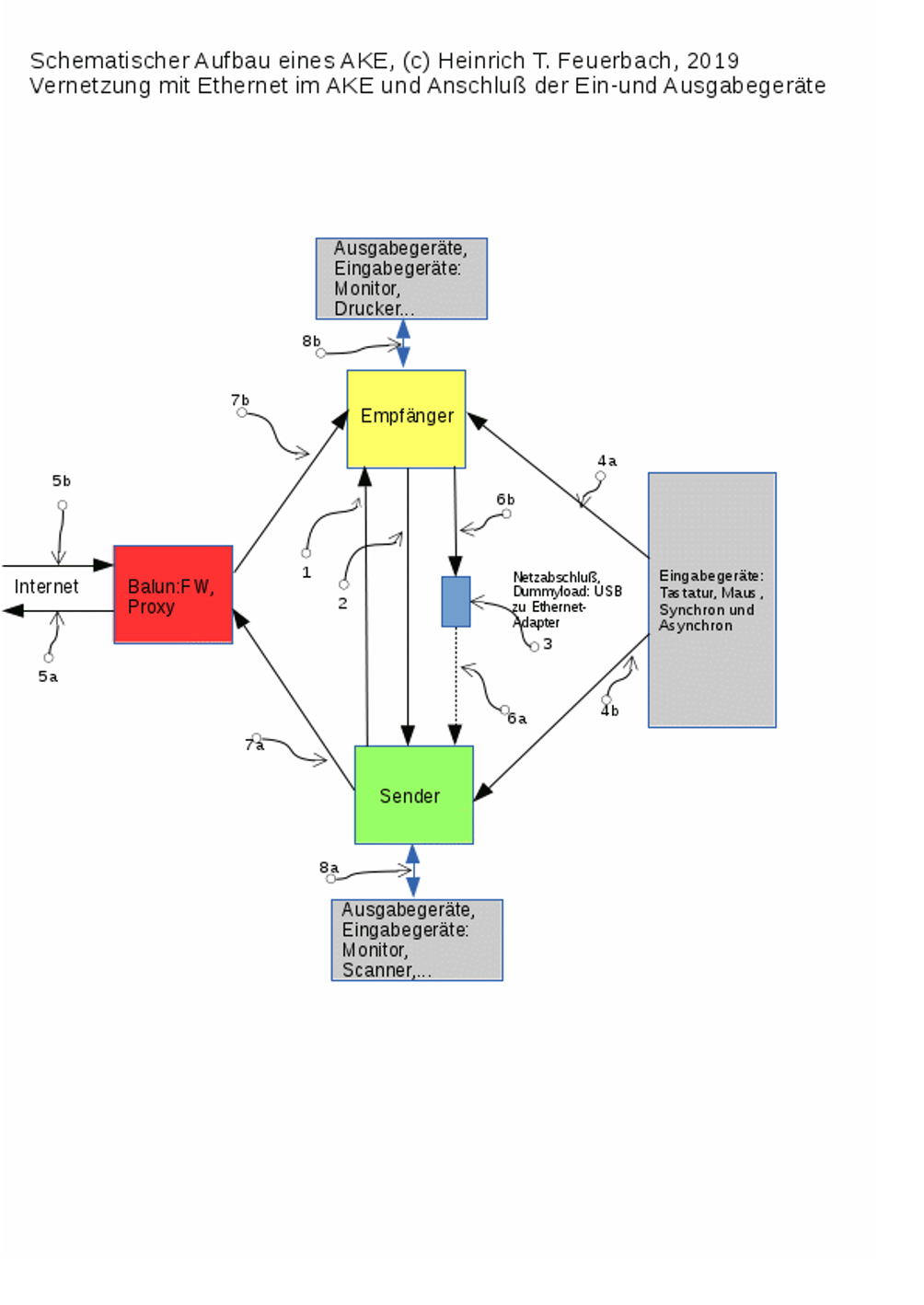
Fig. 1: Network connections between the components of the ACE and external network access (layer 1)
Explanation of Fig. 1: the Red device (“Red” for short, shown with a red background, the “balun”) has two interfaces (IFs) complying with Ethernet IEEE 802.x. One is an external interface connected in the conventional symmetric manner, where all four wire pairs may indeed be used, for example for the 1000BaseT standard. The minimum used here is copper-based 100BaseT (points 5a and 5b). The sending and receiving directions are explicitly represented by points 5a and 5b, just as they would also be provided by dedicated copper lines using wire pairs 1,2 and 3,6 under the 100BaseT Ethernet standard (point 5a: wire pair 1,2; point 5b: wire pair 3,6 of Red).
The other, internal IF with wire pairs 7a and 7b is connected asymmetrically. The “internal” IF uses 100BaseT exclusively, even if the IF itself already supports 1000BaseT. The connection is asymmetric because the transmitting wire pair 1,2 at point 7b is connected to a different IF from the receiving wire pair 3,6 at point 7a.
For Red’s internal, asymmetric IF, only the 100BaseT wire pairs 1,2 and 3,6 are used in every case to ensure the asymmetry, because 100BaseT still has dedicated line pairs (wire pairs) for sending and receiving. With 1000BaseT, however, all four wire pairs are already used for both sending and receiving (bidirectionally) and are therefore unsuitable for asymmetry.
Since Red’s internal IF, points 7a and 7b, uses only wire pairs 1,2 and 3,6, while the unused wire pairs 4,5 and 7,8 are left open, the 100BaseT standard is automatically used even with 1000BaseT, meaning that a maximum of 100 Mbit/s is transmitted. This is due to the backward compatibility of the 1000BaseT standard.
The ACE’s internal network, with the wire pairs at points 7a, 7b and 6a, 6b, is implemented in an enclosure equipped with four RJ45 Ethernet sockets. Twisted wire pairs are used, connecting the appropriate terminals of the RJ45 Ethernet sockets by soldered joints inside the enclosure. A lid is screwed onto the enclosure to close it, providing sufficient mechanical protection against damage to the wires and solder joints. The enclosure is the physical part of the balun transformer, or “balun” for short.
(The exact graphical representation of the balun’s construction is provided in a separate document.)
The external IF at points 5a and 5b provides the ACE’s network connection to the LAN and onward to the Internet.
The internal IF at points 7a and 7b provides the connection from Red to the sender (S) and receiver (E).
Red corresponds to an “airlock” for data, whose inner gate is at points 7a and 7b and whose outer gate is at points 5a and 5b. Red filters and checks data sent by Green, or S, to the Internet, or received from the Internet, before forwarding it to Yellow or to the external network.
Data arriving from the Internet at point 5b is first checked in the balun and, if deemed “good”, is forwarded through point 7b to E, or Yellow. This data normally consists of responses to requests sent by S, or Green, to a server on the Internet or LAN.
These responses, but also requests, cause E, or Yellow, to attempt to send.
Data packets sent by E (the box with a yellow background) pass through point 6b into the terminating interface (the box with a blue background, “Blue”, point 3). For this purpose, E’s, or Yellow’s, transmitting wire pair 1,2 is connected to Blue’s receiving wire pair 3,6 (point 6b).
Blue’s transmitting wire pair 1,2 is connected to the receiving wire pair 3,6 of Green, or S (point 6a).
The connection line at point 6a is interrupted or dashed because it does not transfer any data to Green, or S, but serves only to close the link electronically. Under no circumstances should data be transferred from Blue to Green, in order to preserve the asymmetry between Green and Yellow, or between sending and receiving (S may only send, E may only receive—with the sole exception that E may send “into the blue”).
Blue is supplied with power only, through the two wires provided for this purpose in the adapter’s USB connector. The wire pair for data transmission in the adapter’s USB connector is left open. This ensures that Blue cannot forward any data. Blue may therefore be powered either through a free USB port on a computer or through a commercially available USB charger.
The Green device sends its data as requests to Web servers and so on through point 7a, wire pair 1,2, to Red’s wire pair 3,6. This closes the data circuit formed by these four IFs. Green can now send packets to Red, whereas Yellow can send only to Blue. Responses originating from or passing through Red can be sent to Yellow to be displayed to the user on the monitor.
Since Green and Yellow must be synchronised with each other, there is an additional direct symmetric network connection between Green and Yellow, independent of the four-pole ring network just described. It serves only to send data from Green to Yellow, never in the opposite direction (simplex). All communication in the opposite direction must be prevented to preserve the asymmetry and prevent attacks by Yellow on Green.
This connection can be established outside the balun using a cable connection, with a crossover patch cable or, where the IFs have an auto-crossover function, a straight-through patch cable as well. The corresponding interfaces of Green and Yellow are connected by a short patch cable, for example UTP 5e, at points 1 and 2. Figure 1 shows this connection for the case of 100BaseT, with point 1 representing the sending direction and the only permitted communication direction on this link. Point 2 is the connection not used for data transmission; here it serves only to close the electrical circuit so that data transmission on this link can take place at all.
Bluetooth may also be used as a wireless alternative for this synchronisation connection, provided that only synchronisation data and no “important” data is transmitted wirelessly from Green to Yellow. Otherwise, a layer 5 for encryption should also be used.
When 1000BaseT is used for this link consisting of points 1 and 2, all four wire pairs of the RJ45 connector are, of course, used. Bidirectionality is reduced logically from duplex to simplex by a firewall on Yellow preventing all sending from Yellow to Green, and a firewall on Green preventing all reception of data from Yellow (from layer 2a).
The arrows at points 4a and 4b represent the keyboard connections and the mouse connections.
Asymmetric operation requires a special keyboard that allows simultaneous character input into Green and Yellow (synchronous keyboard). The exact construction of this keyboard and its method of manufacture are described in a separate detailed document.
This keyboard has not just one USB connection but two, one for Green and one for Yellow. Using changeover switches, the user’s keyboard input can also be sent selectively to Green alone or to Yellow alone.
The mouse can be connected selectively to either Green or Yellow through the same changeover switches. This permits asynchronous operation of mouse input. Alternatively, two separate mice can be used, one for Green and one for Yellow.
If laptops are used as the hardware platform, the changeover switches can also be omitted, because the laptops already have a mouse and keyboard built in for asynchronous operation.
The detailed description of the invention’s construction accompanying this patent specification assumes three laptops as the hardware platform for all three devices, Red, Green and Yellow. The detailed description is provided in a separate document. As an exception, when laptops are used, the built-in keyboards can also be used for synchronous operation, using both hands, though this is of course more cumbersome than using the synchronous keyboard.
The present document describes the invention independently of the hardware used, such as laptops, desktop PCs and so on. Further documents describe the exact construction using laptops as an example, with one document per device and for the additional hardware and required software, so that a person skilled in the art can successfully reproduce the invention from these descriptions.
With all types of synchronous input devices, it is important that they cannot establish a “bridge” for data from Yellow to Green, in order to prevent attacks on the asymmetry.
Points 8a and 8b represent the connections from the other input and output devices to Green and Yellow, that is, to monitors, printers, scanners, cameras and the like.
The synchronous keyboard is based on wired USB keyboards. It is made from two conventional keyboards by housing the layout membranes of two identical, commercially available wired USB keyboards, together with their processor boards, in one keyboard enclosure. Each keystroke therefore produces the same character at the same time, which is sent to both Green and Yellow.
To prevent crosstalk between the keyboard processors and attacks on the asymmetry, a grounded shielding plate is placed between the two processor boards. A further shielding plate surrounds the keyboard’s processor area to prevent data signals from radiating to the outside.
Two changeover switches built into the keyboard also allow the synchronous keyboard to be used asynchronously, so that character input can be directed to Green alone or to Yellow alone.
The changeover switches can likewise direct mouse input selectively to Green or Yellow, depending on whether the network is to be used (mouse connected to Yellow) or work is being performed only on Green (mouse connected to Green). When network programs or the network are used, the keyboard is operated synchronously, so that all keystrokes can be processed simultaneously in Green and Yellow.
Equally synchronous operation of the mouse would also be conceivable, so that all mouse movements could be processed simultaneously on Green and Yellow; however, this would also require all graphical display elements (windows, menus) on Yellow to be synchronised by Green. This is not part of this invention; according to the invention, asymmetric use of the network is controlled purely through the keyboard.
Layer 2:
The following three points must be implemented here:
a) The sender (“S”) and receiver (“E”) must have both the same IP address and the same MAC address. This ensures that, under asymmetric conditions, S and E behave like a single network device towards the third device, the balun, or Red. To achieve identical MAC addresses, the program “macchanger” is used on one of the two, Green or Yellow.
b) Resolution between MAC and IP addresses within the ACE network must be static, using appropriate mappings established with the “arp” tool on Red, Yellow and Green each time the systems start, because dynamic ARP requests such as “Who has IP x.x.x.x? Tell y.y.y.y.y.y.” are not possible under asymmetric conditions: the reply to the request would not arrive at the requester but at E.
If E were to send such a request, it would reach only the Blue IF and would therefore achieve nothing.
c) Firewalls on layers 2a and 2b: the firewall programs “arptables” and “ebtables” are used to allow only necessary and desired data flows. This also blocks attack attempts directly at layer 2. The two programs are used in addition to the “iptables” firewall.
Otherwise, Ethernet complying with IEEE standard 802.x-100BaseT or -1000BaseT is used for layers 1 and 2.
Layer 3:
The network layer. It is responsible for routing in networks that comprise more than just one network segment. An application example here is the asymmetric ping utility, which uses the ICMP protocol to allow simple monitoring and functional tests in the network, such as checking the reachability of computers in the network.
For this purpose, the ACE has a ping program on the S side that has been extended with the ability to synchronise the E-side ping program with its requests. Both ping programs are started simultaneously by the user through the synchronous keyboard. S-ping then sends the request through Red into the network to the destination host and sends its associated data (the ping structure) to E-ping. E-ping thereby has the same data state as S-ping, sends the same request itself to the Blue IF (“into the blue”), and thus expects the destination host’s response. As soon as that response arrives through Red, E-ping evaluates it (round-trip time) and displays it to the user on the receiver’s screen.
Merely running the ping program synchronously on S and E is therefore not sufficient.
For asymmetric ping (“aping”) also to be able to leave the ACE’s asymmetric area and, for example, ping a host on the Internet or the LAN, IP forwarding must be enabled on Red. An aping to Red is, of course, sufficient merely to test network functionality within the ACE. This allows all connections within the ACE to be tested.
For the invention, it is sufficient to configure appropriate routes from Green to Red, from Red to Yellow, and from Green to Yellow. Red is, of course, the default gateway for Green and Yellow. Green and Yellow receive the same IP addresses in the same network segment as Red’s internal IF. For manual network configuration, the file /etc/hosts must be populated with the IP addresses of the computers involved. /etc/host.conf is populated with “order bind,hosts
multi on”. /etc/resolv.conv receives the network address of the ACE’s internal four-interface ring network and the addresses of the name servers (DNS servers).
The file /etc/HOSTNAME is populated with the name of the respective device.
All configurations extending beyond these files, such as firewall rules, are set at system startup through a resource script via /etc/crontab. These scripts and other details of installing the three computers are described in the corresponding detailed documents.
Layer 4:
The transport layer. It should be noted here that under asymmetric conditions only connectionless protocols, such as UDP, can be used, because methods requiring duplex communication, such as TCP’s “handshake”, among others, are not possible in a purely simplex network such as that of the ACE.
Among other things, two proxies are implemented on Red for this purpose: one is a conventional proxy called “squid”, which forms the frontend for web communication towards the outside, that is, towards the Internet, and is mainly intended to enable the HTTPS protocol. On squid’s internal side (that is, in communication with Yellow and Green), only HTTP is “spoken”.
The next proxy further inside Red is cproxy, which was created for the ACE’s purpose. The “c” in cproxy stands for client, because this proxy is required separately for each ACE and protocol.
In the invention, squid and cproxy are implemented or installed on the same hardware, the same single Red device, but they could also run on separate hardware if those devices were networked symmetrically with each other.
While squid still communicates symmetrically on both sides, cproxy communicates symmetrically only with squid, that is, towards the Internet. Towards the green side, that is, towards Yellow and Green, it communicates asymmetrically, transmitting towards Yellow and receiving from Green.
In broad terms, cproxy performs the following functions:
a) Balun software: cproxy converts the connection-oriented TCP used for HTTP on the Internet
into connectionless UDP for Yellow, or converts the UDP used by Green into TCP for the respective web server with which the user is currently communicating through their browser.
b) cproxy forms an application-layer firewall: it filters received web content, for example to remove scripts, if this is desired. The ACE user can control cproxy’s filtering behaviour through short commands entered into the browser; see Layer 7.
c) As an auxiliary program for carrying out the symmetric communication with the Internet that the asymmetric, green side cannot perform: DNS name resolution for websites and the like is carried out by cproxy. If images, scripts or CSS belonging to a website are also to be displayed to the user in the browser, cproxy initiates the “additional loading” of this content and then sends it to the browser on Yellow. Loading additional website content as needed is necessary because the initially transmitted bare HTML page does not contain all the content, such as images, CSS, scripts and so on, but only references to it; however, since the receiving-side browser can only transmit into the blue, it cannot follow these references or load their content. cproxy therefore takes over this task as required. To do so, it loads the resources and sends them first to E, which stores them locally. References to resources residing on the server are converted into local references, and the HTML page modified in this way is then sent to the receiving browser. This browser reads the now local references and subsequently loads the resources, such as images and CSS or scripts, locally from its disk, since they were copied there beforehand. A dedicated server process runs on E to receive and store the resources in advance. Note: automated “additional loading” of page resources such as CSS, images, scripts and so on has not yet been implemented at the present stage. However, manually loading individual images by short link is possible.
Without these auxiliary tasks at protocol level performed by cproxy, it would scarcely be possible to use the usual protocols in the usual way, or it would require substantial changes to the network programs. cproxy also negotiates communication with the web server: by default, cproxy sends requests to the respective web server using HTTPS. Only if the web server does not want this and requires plain HTTP does cproxy send the user’s request again, this time requesting HTTP. cproxy therefore constitutes an HTTP proxy. In principle, however, it could process other protocols in the same way. For each protocol offered, a separate cproxy is required on Red to accept S’s requests on the corresponding port.
The counterparts to cproxy are located on Green and Yellow respectively: the “lproxies”, with “l” standing for “local”.
These convert the browser requests arriving over TCP on Green, or S, into UDP and then send them to cproxy. On Yellow, by contrast, lproxy converts the web server’s responses from UDP back into TCP so that the browser there can process them, because browsers only know TCP.
Layer 4 also includes ports, that is, the numbers assigning network applications to the data packets that an interface sends or receives.
For the invention, a problem similar to that of asymmetric ping had to be solved here so that asymmetric communication could also work on layers higher than Layer 3: port synchronisation.
Since the source ports when sending a request to a web server are selected internally by the operating system and differ unpredictably with every request, the web server’s response would be sent to the sender’s dynamic port, that is, Green’s, instead of the port that Yellow used as its source port. The source ports on Green and Yellow therefore not only change with every request but are also different from each other on every request. The difference between Green’s and Yellow’s source ports is the problem. It causes the server response to be sent to the wrong port and consequently not processed by the browser on Yellow. The source ports must therefore be synchronised. The simplest solution to this problem, and the one requiring the least intervention in the system and existing programs, is to standardise S’s and E’s, or Green’s and Yellow’s, dynamic source ports by means of a firewall rule. For this purpose, each Layer 4 firewall, here iptables, is given a rule that changes its respective dynamic source port to a predefined port. Since the dynamic source port on S and E is now mapped to the same static source port, S and E ultimately use the same source port for their requests. The web server’s response thus reaches its destination in E, and the page is displayed in E’s browser, the “receiving browser”. In the process, the static source port of the response packets is converted back by the firewall on Yellow into the respective dynamic source port. Unfortunately, however, the same static source port cannot be retained permanently in the firewall rules for all requests, so it must be changed for every request. This is due to the iptables program. A client was therefore created on S that transmits the static source ports at certain time intervals to a matching server program on E, ensuring that S and E always use the same static source ports when the user makes a request to a web server. To do this, the client program sends its current static source port as a number to the corresponding server program on E. The server program then inserts that same static source port into its firewall rules. S and E thereby send their UDP requests with the same source port.
On Layer 4 too, E transmits into the blue, that is, into the terminating IF, in order to be ready to receive.
Since all data in the ACE is intended to originate from Green, a client-server pair of programs is required that can also transfer entire files under asymmetric conditions from Green to Yellow, from Green to Red, and from Red to Yellow. This and other tools are described in detail in further documents, and their source code is listed there.
Layer 5: see Layer 7.
Layer 6: see Layer 7.
Layer 7:
The application layer. In the ACE, applications on this layer cannot communicate independently with the outside world, the Internet or other networks, because E cannot transmit, while S receives no requests from outside that it could answer autonomously without the user.
Consequence: if the user has opened a website that in turn contains a request to, for example, an advertising provider or a statistics server, the associated request or packet goes only into the Blue IF, and therefore has no consequences. Malware “picked up” through a website can likewise no longer “load additional” programs in this way. (Layers 5 and 6 are usually integrated into Layer 7 here.)
cproxy forms an application-layer firewall: it filters received web content, for example to remove scripts, if this is desired. The ACE user can control cproxy’s filtering behaviour through short commands entered into the browser and thereby determine whether scripts are to be loaded, whether images are to be loaded (the latter still needs to be implemented), and so on. The less is loaded, the faster the page appears in the browser and the safer browsing becomes.
The network applications are the same as in the symmetric case. However, the applications are maintained in duplicate, once on E and once on S. There is therefore always a transmitting and a receiving version of the network program.
cproxy replaces both the HTTP header and HTTP error messages coming from the web server with its own standard content in order to prevent attacks on the browser (the so-called user agent) through manipulated headers or HTTP error messages.
Layer 8:
The control layer, for representing the ACE in the ISO/OSI layer model.
The ACE user, with their (synchronous) input and output devices as the interface to the ACE, constitutes Layer 8. Only on this layer is the data circuit closed in the ACE, for example by triggering responses to requests or initiating requests themselves.
All the components of the invention mentioned above, insofar as they are implemented in software, are initialised or started at ACE system startup by their own respective scripts. The script also contains the firewall rules for each of the three computer systems and other network initialisation settings for MAC and IP addresses. SuSE Linux 13.1 on AMD as well as Intel-based hardware was used as the operating system. However, the invention is not tied to a particular operating system or platform.
The keyboard is implemented as a synchronous input device. To be able to operate both computers, the sender (“S”) and receiver, simultaneously, that is, to submit a request to a web server on both at the same time, the hardware components of two conventional USB keyboards are assembled into one shared keyboard with two USB connections. Beneath the keys there are therefore two keyboard membranes instead of one. The same keys thus actuate two keyboard membranes, each with its own processor.
This allows requests to be sent almost simultaneously, for example to web servers or to asymmetric ping.
(Synchronous mice would also be possible according to the same principle. However, further synchronisation programs between S and E would then also be needed, because the windows and mouse positions on S and E, and all other graphical displays on S and E, must always be in the same position. This has not yet been implemented here.)
In the invention described here, a single mouse that can be switched between S and E as needed is sufficient. Two individual mice, one each for S and E, can also be used.
When browsing websites asymmetrically, the onward links displayed there cannot be followed directly by clicking with the mouse, because, due to the asymmetry, the receiver on which the link appears cannot transmit back to the Internet. A different method must therefore be used. For this purpose, cproxy, which has the page’s entire content available to it, prefixes each link with a so-called short link (“KL”),
which the user sees as a five-digit number, for example 00546. To follow, that is, open, such a link, the user specifies the prefixed KL number with the prefix “x.”, thus x.00546. The user enters this into the browser’s URL field, which, because the keyboard is synchronous, takes place equally on S and E, even though the user sees only E on the screen. Pressing Enter then sends the KL “x.00546” from E into the blue, but from S to Red. On Red, cproxy receives the KL and evaluates it by converting it back into the corresponding actual link, the long link (“LL”). To do so, cproxy maintains a table for each website pairing the LLs with the KLs.
After converting the KL to the LL, cproxy sends a corresponding request to the associated web server, which sends back the response. cproxy filters the response and then forwards it again by UDP to E on Yellow. On Yellow, lproxy converts UDP back into TCP, and the firewall converts the destination port in the response packet back to the browser’s dynamic port. All communication conditions are thus satisfied, and the browser on E displays the server response, that is, the page behind the link.
The synchronous keyboard may also have two switches that allow it to be used for simultaneous input on S and E, or for input only on S or only on E. The switches’ synchronous setting is used when operating network programs; the monitor is then set to E, as is the mouse. When operating only one computer, S or E, the switches are adjusted accordingly. This is then asynchronous mode.
Sequence when browsing the web:
When browsing the web, the user first enters an ordinary link into the browser’s URL field through the synchronous keyboard. To do this, the Control-L key combination is entered synchronously. The text input cursor is thereby placed in the URL field in both browsers, equally on Green and Yellow. The user now synchronously enters the desired link, prefixed with “y.”. This prefix is used for normal links (LL) and enables cproxy to recognise a user request. The user then sends the request to Red by pressing the “Return” or Enter key. Since this takes place synchronously, the receiving-side browser also sends out this request, but not to Red: it sends to Blue, into the blue IF. The receiving browser is thus now ready to receive and waits for the web server’s response. The request packet sent from Green to Red is received by cproxy, and its content is evaluated. This request now proceeds to the squid proxy on Red. Squid queries the IP address behind the web server’s name and then sends the request to the web server. The response from the web server returns to squid, which forwards it to cproxy. As a Layer 7 proxy, cproxy filters the content to remove unwanted material and creates a table containing short links (KLs) for all links that remain in the website after filtering. These KLs are prepended as prefixes to the titles of the links in the website’s HTML so that the user can see them. The website modified in this way is now sent by cproxy in a uniform format (content encoding, uncompressed) to Yellow, where the browser displays it to the user. The user now sees the requested website. All of the page’s links are prefixed with KLs. If the user now wants to navigate to, or load, one of the links on the page, they press Control-L again, which takes them synchronously to the URL field on Yellow and Green. There they enter the KL prefixed with “x.”. Example: “x.00234”. KLs have five digits with leading zeros and are entered into the browser as five digits. After Enter is pressed, a request with the KL is sent from Green to Red and, simultaneously, again from Yellow to Blue. cproxy now resolves the KL into its corresponding long link, LL, and sends it as before as a request to squid, which establishes the connection to the server. The sequence is then the same as before, until the website is displayed to the user on Yellow. Images that would actually be embedded into the website when loaded subsequently by the browser are displayed as KLs. The user can use them to load images individually and then save them as well. Through prefixes entered into the URL field, cproxy can be configured at runtime to allow scripts through or filter them out, among other things. cproxy does not need to be restarted for this: it evaluates the content as a request and thereby changes the program flow according to the instruction. The user can therefore control cproxy’s behaviour at any time. For example, the command “s.tls” can cause requests to be made using HTTPS (the default in cproxy after startup). The command “s.tls-” causes subsequent web requests to be made using HTTP. All commands can be combined freely.
In the current version, the website is displayed without CSS and images, that is, as it is initially delivered by the server, without loading additional resources.
Passive use of the “WWW” is thereby implemented.
Note: before entering a new LL, KL or control command synchronously into the URL field, the user should synchronously press the Escape key to return the browser to its initial state first, because the loading process may not yet have stopped.
Sequence of the communication described above on Layer 4:
After the user has entered a link into the URL field and pressed Return, the browser sends a DNS request, which is always answered by the local DNS with the Red device’s IP address. The browser thereby sends a TCP request to port 8070, initially received by lproxy on Green, because the transmitting browser is configured to use a local proxy. lproxy converts this request from TCP into UDP, because only a connectionless protocol can be used under asymmetric conditions. This UDP request is modified by the iptables firewall: lproxy’s dynamic source port is replaced with a static one from the range 50000 to 50999. This static port is specified to the firewall by the port synchroniser. The port synchroniser also sends a port from the above range to the receiver, where a service passes it to the firewall on Yellow as well. Yellow will therefore use the same source port as Green when transmitting synchronously. Only this ensures that the receiving browser waits for a response on the same port from which the sending browser sent its request. Without port synchronisation, no communication along Green–Red–web server–Red–Yellow could therefore take place. After the request packet with the static source port has been sent from Green to Red via UDP, it is received by cproxy on port 80. Following an input check, the data content is forwarded as TCP to the squid proxy on port 8080 on Red, or within Red. Squid, in turn, first sends this to the web server as an HTTPS request. If the web server supports HTTPS, the encrypted connection between squid and the web server is established. If it does not support HTTPS but only HTTP, an error message is sent by squid to cproxy, whereupon cproxy sends the same request to squid again using HTTP. There is then a TCP connection to the web server. The web server’s response is sent to squid, which then forwards it as HTTP to cproxy, even if squid maintains an HTTPS connection to the web server. cproxy can therefore read and filter the data. It then forwards the response by UDP to the source port (the static synchronisation port) on Yellow, where the local lproxy converts UDP internally on Yellow into TCP for the browser. In the process, the firewall on Yellow converts the static source port into the dynamic port used by lproxy, which here is the destination port. lproxy communicates with the browser over its TCP connection, and the browser finally displays the website to the user. The data circuit is thereby closed for this user request.
Attack matrix for systematising all attack paths and targets:
The attack matrix (“A”) is a diagram intended to clarify the possible attack paths and possible attack targets, authored by the applicant. In other words, all conceivable attacks on a networked computer system (excluding local attacks on an IT system on site, that is, physical access by a person) have a place in at least one of A’s fields and can therefore be clearly assigned to one of the fields.
The nine main fields, resulting from the three columns for the three attack paths and the three rows for the three attack targets, are subdivided again, mostly into fields for known or intended networks and fields for unknown networks, which are therefore more likely to be unwanted by the user.
An example of an intended network is the Internet, if it was configured by the system’s user. An example of an unwanted network (from the system administrator’s point of view) is an uncontrolled side entrance into an organisation’s local network, established, for example, through a mobile phone that has Internet access, and so on. The objective is to cover all fields through technical measures. For if all fields are covered, successful attacks on the overall system are no longer possible.
Notes: almost all fields are divided into known and unknown networks. When one of the field designations is used in this document, it should be understood as including all the other fields located further down or to the left in A. Example: “B3 security” includes securing fields A1, B1, A2, B2 and A3, B3, unless otherwise specified.
The invention protects only fields for known networks.
Examples of unknown or unwanted networks include:
- “Air interfaces”, that is, all kinds of radio modems in mobile phones, smartphones and the like.
- The use of ultrasound for communication, for example between smartphones and with other systems such as televisions, PCs, etc.
- The electricity grid for data transmission.
- Infrared, as used in remote controls.
- And many others.
Program code
All programs required for the ACE are written in the “C” programming language and listed in the detailed documents. This version of the programs allows the user of the ACE presented here to “surf” or “browse” websites. Images can also be displayed and downloaded manually when requested by the user. Images can be saved locally.
The program “aping” is derived, as a network tool, from the familiar “ping” program and operates under asymmetric conditions.
In addition to the programs written in C, startup scripts written as shell scripts are also required on each computer involved in the ACE; these implement, for example, the firewall rules. These scripts are started with the system through a “reboot” entry in the system file /etc/crontab.
The following tarball contains the installation instructions and source code for the laboratory model (“Proof of Concept, PoC”). Note: the file designations in the tarball, such as “RR”, “GG” and “RG”, identify the individual devices: Red (RR), Green (GG) and Yellow (RG), that is, balun or proxy, sender and receiver. The file InstallLaptop_Balun_V.1.0, by contrast, describes the construction of the box containing the ring network of the four interfaces.
Overview Presentation ACE (.pdf)
AKE_PoC.tar.gz MD5: d66882d464d6a2c523d8c45c4b948343, SHA256: 3c2e1f9f30ed78f031976d1c8d2d2dd0a3d9dd2a104241ed812957ba929a0da1 Size: 7889043 Bytes AKE_PoC.tar.gz.sig Certificate fingerprint: 92FA6FA30EF95B03346F57D8F4E66A3232C81156 32C81156.asc Certificate.
Author: Heinrich T. Feuerbach, February 2019